Sunday, October 23, 2011

Berita Kapal

Berita Kapal Mengabarkan Berita Pelaut Indonesia

Satu lagi blog tentang pelaut indonesia.

Berita kapal yang di posting dari http://berita-kapal.blogspot.com, menggunakan platform blogspot yg mudah dan sangat dikenali semua orang di dunia maya ini, Berita Kapal mencoba hadir untuk mengabarkan berita-berita dari para pelaut dan untuk pelaut indonesia.

Semua informasi yg hadirkan sangat lengkap dan up to date banget, para pelaut bisa memperoleh berita tentang apa saja, yang lagi sedang dalam masa pendidikan bisa memperoleh artikel-artikel yg sangat berguna tentang kapal sejak dari rancang bangun dan tata cara pengoperasian kapal dengan benar dan baik.

Dan buat pelaut yg lagi mencari informasi lowongan pekerjaan dikapal bisa mendapatkan informasi lowongan kerja pelaut terbaru yg senantiasa di update dan diperbaharui.

Dan masih banyak lagi informasi lainnya, tunggu apalagi segera kunjungi situs berita kapal satu-satunya di dunia maya hanya disini

Berita Kapal hadir dengan slogan barunya "Mengabarkan Berita - Berita Dari Pelaut Untuk Pelaut Indonesia"

Friday, October 14, 2011

Software for Download

Belows link for download of marine surveying and marine cargo survey references.
1. Convert For Windows by Josh Madison (freeware)
Convert is a free and easy to use unit conversion program that will convert the most popular units of distance, temperature, volume, time, speed, mass, power, density, pressure, energy and many others, including the ability to create custom conversions.
Download available at http://jfmstatic.net/convert.zip
2. ASTM Table 54A by Boriss Grahlovskis (freeware)
All calculation in program based on ASTM Table 54A – Generalized Crude Oils of Volume to 15 C againts Density at 15 C.
Download available at http://deepblueseasoft.narod.ru/exe2008/Table54A.exe
3. ASTM Table 54B by Boriss Grahlovskis (freeware)
All calculation in program based on ASTM Table 54B – Generalized Products Correction of Volume to 15 C againts Density at 15 C.
Download available at http://deepblueseasoft.narod.ru/exe2008/Table54B.exe
4. ASTM Tables Program by Goldware (freeware)
API Specific Gravity and Density Converter, Weight Correction Factor (WCF), Gross Standar Volume (GSV) Conversion Factors and Russian Calculation by Captain Ioannis Filippou.
Download available at http://sevensurveyor.com/x2323l/dlall/ASTMTablesProgram.rar
5. Petroleum Calculations Program by Donald R. Huckabee (freeware/shareware)
A petroleum calculation Program. It is shareware and may be distributed freely. Table associated in program are ASTM 5A & B, 53A & B, 6A & B, 54A & B. Also Temperature conversion, Gravity Conversion, Gauging, Addictive and Calculator.
Download available at http://sevensurveyor.com/x2323l/dlall/WPetrol.rar

Jika anda merasa info ini berguna, silahkan anda bisa mendonasikan sedikit rezeki anda dengan mengklik link dibawah ini:
 

Sumber : sevensurveyor.com

Draft Survey Software


Forward Draft Survey Software
Forward Draft
Selain program perhitungan DraftSurveySoftware.com ,kami memberikan pilihan program gratis perhitungan draft survey software disini, ikuti link tautan dibawah ini:
7S DraftSurvey Software, Password : 65GTW3KC3KQP
Bagi anda yg membutuhkan program perhitungan minyak untuk petroleum produk seperti bensin, solar, minyak tanah dan lainnya dapat mengunjungi situs ini http://calculationpetroleum.blogspot.com/
Dibawah ini kutipan blogwalking artikel Draft Survey Softaware:
I have tried to complete the sevensurveyor project and developed one simple software for draft survey calculation named 7S DraftSurvey.
This software is made for automatic draft survey calculation such as; quartermean draft, trim, fore and aft draft corrections, Displacement, TPC, LCF, MTC, 1st & 2nd trim corrections, density correction and deductibles. The software could be used to determine the total cargo loading/unloading on the ship board.
It is very simple and helpful to cut-down the time for draft survey calculation. What you have to do is just inserting some data in the initial draft survey and get easy calculating for any intermediate and final draft survey with insert the reading draft, density and sum of deductibles only. This software designed to handle the ship with reading draft marks up to 27.00 Meters.
You also could save the draft survey report and the ship data along with the program. In case, the ship that you have ever made survey previously then back again to load or unload at another times, you only need to copy and paste data for the saved data and calculate the draft survey.
Now, the access will give you the chance to try this software with download link atTrial_7s Draft_Survey_Software and includes the manual (total size: 309 kb). This software is required password : 65GTW3KC3KQP.
I think you will be like this software, let me know by drop your comment.

Download Software for Surveyor

In the short time, I have received some emails and comments that requested the petroleum calculation software and ASTM Table. To fulfill it, I have loaded some free and simple software that may help surveyor to do their assignment in Bunker and Petroleum Survey. These software is not as complete as the version that selling online, but it’s handy and useful.
Just go to this link for downloading: http://sevensurveyor.com/software/. The list of software will be growing, I will load additional Software when available.
Just leaving your comment about Software for Surveyor.
Regards,
Surveyors / 65GTW3KC3KQP
PS: If you need the complete calculation software you could search on the web, it is available to buy online. For the ASTM Table complete version, you could check at this linkhttp://astm.org.

The accuracy of Draft Survey is a big question?

Sometimes the accuracy of Draft Survey is a big question, especially when the cargo loaded or discharged from the vessel shown extremely different weight with the references Weight Scale or Counter Weight. Unfortunately, the parties concerns would be doubt on to the weight resulted by Draft Survey, as they have been relying upon the mentioned scales for many years.
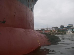
Draftmark 300x225 Draft Survey: The Accuracy and Factors Effecting
Draftmark
The Draft Surveyors as the person in charge should be solve this issue to prevent any claim in the future. Where is the doubt came from? The next investigation is required to calm down these issues.
Draught Survey UN ECE: Code of Uniform Standards and Procedures
UN ECE was published the Factors Affecting Draft Survey as follows :
1- Incorrect hydrostatic information or draft marks: Investigations carried out in specially performed draft surveys have indicated that there can be significant errors in the determination of displacement due to typographical errors or arithmetical errors in the ship’s hydrostatic tables. This could be improved if the tables furnished to the surveyorbore an approval stamp by the flag government or the classification society. A number of years careless re-painting of draftmarks, especially if they have not been permanently marked on the hull, can cause erroneous readings. If there is any doubt, the draft marks should be re-sited at the next dry-docking.
2- Incorrect tank calibrations: This is normally ascertained after a number of draft surveys when a constant error may appear. It may be verified by a carefull draft survey when just the tank(s) in question are filled or emptied with no other weight changes. Clasification societies, upon request of the shipsowners, may however issue the special calibration certificates for each compartment of the vessel.
3- Mud and/or scale in ballast tanks: The quantity of mud and/or scale will increase over a period of years, depending on the sediment in any ballast taken, on the extend of scale formation and on the cleaning which is carried out. It is very difficult to quantify. The effect on ballast calculations can be minimized unless there are reasons to the contrary by leaving a measurable quantity of water in the ballast tank instead of pumping it dry. The calculation would then use a difference in known water quantities rather than assume that a tank is completely empty : in this way the error would be confined within the density differential of the mud and the ballast water. Regularly large bulk carriers arrive at unloading ports with a slight trim by the head as a result of burning fuel from the aft located fuel tanks during long sea passages. Since generally the sounding pipes are located aft only, dry soundings of ballast tanks do then not necessarily mean that no water is present, since any water will accumulate in the fore end. When the ballast tables are subsequently entered with zero sounding and the head trim, considerable quantities of residual ballast water are found. Again, this water does not actually have to be present. Consequently, when one assumes empty or tabulated quantities, both may be wrong.
4- Bottom shell growth: Marine growth on the bottom of the ship, especially if dry docking is delayed or if there is a failure in the anti-fouling paint, adds weight to the ship. But, because this weight should not change between the start and finish surveys, it has no effect on the calculation of the cargo weight, unless the vessel is docked for a long period or the antifouling paint deteriorates.
5- Water disturbance: Normally due to wind, swell or passing traffics. Accurate reading of the draft requires the use of a draft reading tube.
6- Variations in seawater density: If a loaded vessel has a small underkeel clearance, the seawater may hold mud/sediment in suspension, or chemicals in solution could effect its density. This may be apparent from the bottom layer sample. If it is suspected, a sea water sample should be taken from the maximum draft as a check. In river ports or in proximity of river mouths or of industrial plants, there may be numerous layers of water with differing densities, which may substantially affect the accuracy of the water samples unless properly detected.
7- Vessel squat: When a vessel is moored in a tidal stream or a fast flowing current, in shallow water, it will squat in the water, i.e. its draft will increase. This is due to the fall of the pressure of the water between the bottom of the hull and the seabed. The sinkage is due to a number of complex factors due to the hydrodynamic properties of the hull, especially where underkeel clearance is small and which cannot be accurately determined by theoretical calculations. There appears to be no effect at current speeds below 2,5 knots. If conditions are inductive to squat, the surveyor and the master should monitor carefully that the vessel is fully afloat and not touching the bottom and for best accuracy, consider waiting for slack water, or shifting the vessel to another berth where the effect of squat are known to be less or absent.
8- Asymmetrical hull deflections: If the mean draft midships differs from the mean of the forward and after drafts, it is assumed that the deflection of the hull shape takes the form of a parabolic curve. This assumption is inherent in the two-thirds and quarter-mean methods of correcting for hull deflection. If there is no difference between the mean draft midships and the mean of the forward and after drafts, it is assumed that the hull shape has not been deflected. Both assumptions may be incorrect. In practice, the hull deflection may not be a parabolic curve or there may be deflections between the ends of the vessel and the midship points (i.e. as a modified sine curve). If the draft is not read at all six draftmarks, the hull may be twisted without the fact being known.
9- Solar bending: Vessels of approximate 50.000 mt deadweight and upwards, may be subject to hull deflections caused by solar bending of the deck and structure above the waterline. The effect would normally be a hogging which can be appreciable. Some readings taken on a 74.000 mt dwt bulk carrier and reported in “Seaways” (March 1987), showed that the fully loaded vessel was sagged 5 cms at 07.00 hrs and 27,5 cms at 17.00 hrs on the same day with no movement of weight within the vessel (apart from normal oil/water consumption for an anchored vessel).
10- Use of approximate methods for corrections: The mathematical methods used to correct for trim and/or hull deflections, if these conditions exist, are approximations because of limitations of time, expense and the work site. However, if the same methods are correctly and uniformly employed in all surveys, the resultant error in the exact cargo weight will be minimal. However, if in better equipped ships, correction tables for trim and/or hull deflection are available, then such tables should be used instead of the approximate methods.
11- Draught gauges: Draught gauges may be very helpful as a check, but should never replace the reading of draughts using the fixed draught marks on the ship’s hull.
12- Squat: While measures the draught, when there is a strong current running and there is water depths of less than twice the draught of the vessel, the draught readings may be misleading, due to the effects of squat. The survey report should include reference to Possible Squat Effects, even if a suitable correction to the draught readings cannot be determined.
13- Anchors and Chains: The anchors may be in the housed position, where they contribute to the lightship, or they may have been used in the mooring of the ship. Then the anchors will be on the sea bed along with a given length of cable. The loss of weight due to its removal is weight taken from the light displacement, this amount should therefore be added to the quantity of cargo. There should be information available on board to enable the surveyor to establish or calculate the weight of the missing anchor and cable.
In case of the chain cable, it can be calculated with reasonable accuracy by the following formula:
Weight per shackle (Tonne)  =
15 x (link diameter in cm)2 x 3,87
——————————————
1000
The link diameter is the diameter of the steel rod, which makes up each individual link. In the case of the anchor itself, this will vary from ship to ship, but this information should be available on board. This anchor weight should be rounded to the nearest half tonne.
Draft Surveys – Volume And Weight Calculations:Draft Surveys are to determine the quantity of cargo loaded in, or discharged from a vessel or barge and are dependent on the fact that the vessel or barge is always afloat, and that all the drafts are visible.  Some of the common problems during draft surveys one should always be aware of are:
* Unusable sounding pipe – i.e., inaccessible, blocked or broken
* Ballast holds, which are poorly calibrated
* Tunnel space/duct keel that cannot be sounded
* Loaded vessel aground prior to commencement of discharge
* Loaded vessel aground after completion of loading prior to sailing
* Listed vessel, which has its effect on displacement and soundings of liquids in tanks and other spaces
* Weights other than the cargo, ballast, or consumables that are not the same between the starting and the finishing surveys.
Surveyor’s opinion:
All the above are very clear explanations and guides. Additionally, Surveyors has concerned to Draft Mark Reading. Draft Mark reading is the essential part of Draft Survey, where the Draft Survey is begin from the reading part. The vessel’s staffs cooperation is needed to success the good reading. The following are some rules to get the best result :
- Vessel is secured properly,
- No any ship’s gears movement allowed at the time, (such as crane, derrick etc),
- No any ship’s liquids transfer activity allowed during reading, (ballast, fresh water, fuel and diesel oil),
- Read the Draft Marks as close as possible, taken pictures for the next clarifying,
- Use the small boat to read close the Draft Marks, do not see it from the ship’s maindeck,
- Find the draft in meter first then continue with centimeter to prevent big error.
- For the heavy swell sea condition it is recommended to read and record 12 times, taken out 1 biggest and 1 smallest of the reading results, and make an average draft from the 10 results remained.
To know more, kindly refers to the previous post of Draft Surveys : Terms of Conduct,Procedures and Calculation, and Specimen of Calculation.
Do you have any issues regards this? please drop down your comments here.

Bunker Survey Calculation

In my last post How To Conduct Bunker Survey, I have explained the general step for Bunker Survey conducts. Now, the topic is about the way to calculate ship bunker that we have found on the ship tanks. It is suggested to read the last post to become familiar with calculation.

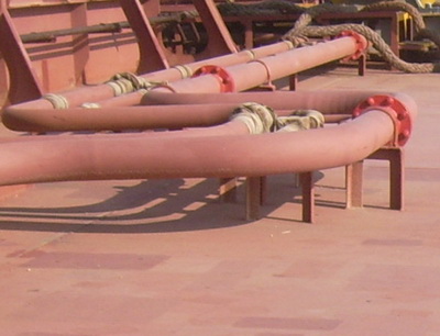
pipe Bunker Survey Calculation
Bunker Survey
The bunker calculation is simple and needs the following:
- Tank Sounding data and Tank Capacity Table. The Corrected Sounding means below is the sounding after correcting with vessel’s trim and list.
Temperature of Oil on Tanks,
- Oil Density @15C,
- Table ASTM 54B (VCF) and Table ASTM 56 (WCF).
Now we could go with sample of 1 tank to test the calculation.
** Question :
FO Tank No. 1 Center, Corrected Sounding = 3.27 Meter, Temperature = 34 degrees celcius, Density @ 15 C = 0.9870.
Tank Volume at Sounding 3.20 M = 157.20 Cubic Meter, at Sounding 3.30 M = 163.60 Cubic Meter.
** Answer :
- The Quantity in Metric Ton = Oil Vol x VCF x WCF,
- Observe Volume = {(3.27 – 3.20) / (3.30 – 3.20) x (163.60 – 157.20)} + 157.20 = (0.07/0.10) x (6.40) + 157.20 = 4.48 + 157.20 = 161.68 Cu.M.
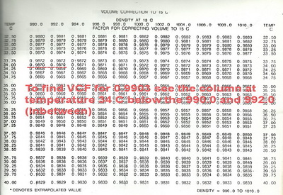
- T 54B (VCF) > Density @ 15C 0.9903 at 34 C = 0.9870 (see the picture below you need to interpolate if any different numbers on both columns).

table54b1 Bunker Survey Calculation
ASTM Table 54B
- T 56 (WCF) : Density @15C 0.9903 at  34 C = 0.9892 (Quick formula with reducing factor for WCF is Density @ 15C – 0.0011 = 0.9903 – 0.0011 = 0.9892). We don’t need to see the table anymore.
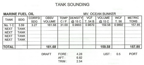
- So, The Quantity in MT is 161.68 x 0.9870 x 0.9892 = 157.85 MT. Sample calculation tanks sounding attached below.
tanksounding Bunker Survey Calculation
Tank Sounding
Note : If you do calculation with Volume in Barrel, just uses ASTM Table 6B for VCFASTM Table 11 for WCF in Long Ton and then ASTM Table 13 for WCF in Metric Ton.
Just drop your comments around this topic.

Regards,
Surveyors

Sumber berita dan gambar : sevensurveyor.com

How to Conduct Bunker Survey?

What is Bunker Survey? The survey is carried out to measure and ascertain the quantity of Bunker onboard at the specific time. This survey is produced the report that states the amount of bunker, usually Fuel Oil (FO) and Diesel Oil (DO), and sometimes Lubricating Oil (LO) is included.
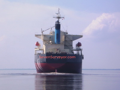
ships How to Conduct Bunker Survey
Go Sailing
Commonly this is done prior to and after a time charter period than mentions as On Hire Bunker (prior) and Off Hire Bunker (after), the Bunker Survey is required to check the amount Bunker transferred or supplied onto the Ship’s Tanks. This job is associated with Ship’s Chief Engineer, the Person who responsible for bunker onboard.
In this post limits to how to conduct the Bunker Survey on the ship tanks only.
Survey Tools required for Bunker Surveyor
-        Notes Book,
-        Sounding Tape,
-        Thermometer,
-        Density Meter for Oil (0.750 -1.000),
-        Oil and Water Paste,
-        Petroleum ASTM Table 54B (for Product Oil) and Table 56,
-        Google and Glove,
-        Flashlight,
-        Sampling Can,
-        Bottle or Can for Sampling (if required taken samples).
Steps for Conducting Bunker Survey
-        Identify and records the number and Depth of Tank, Reference Height, and Measuring Method recommended to use (Ullage or Sounding) for each Oil Tank. Sounding is determined the level of liquid tank from the bottom of the tank to the liquid surface (typically applied for light liquid). Ullage means to determine the level of liquid of tank by measured the empty space from top of the Tank (the mouth of Sounding Pipe) to the liquid surface (typically applied for heavy liquid). The both methods will point to the same result.
-        Record the Last Bunker Report, Time and Place of last Bunker supplied, includes the Oil density.
-        Records the quantity of bunker onboard when the ship arrives at Port (arrival Condition) as per Engine Log Book.
-        Checking the accuracy of the Sounding Tape, it is recommended to use your own Sounding Tape. In case we used Ship’s Sounding Tape, please checking the tape.
-        Sounding each Oil Tank and records the level of Oil on the tank. Attached the sounding Tape with Oil Paste to make easy and clear to show of oil level (recommended for Light Oil).
-        Check the Ship’s Draft Marks to get the Ship Trim for Trim correction, and check the ship Inclination or Listing for List Correction, that is required to calculate the Tank Quantity Table.
-        Taken Oil sample, check temperature and oil density, for the accessible tank only. The Service and Settling Tanks are not accessible due to the oil on that tanks were in heating condition at the high temperature. We could records the tank gauging for determining the quantity, the temperature at the thermometer available on each tank, and the Oil Density from the Engine Log Book. If you could not taken the oil sample for checking density, it is recommended to calculate the Density Commingle, by means the Combine Density between two Oils (Old and New Oils) that has mixed on one tanks which they have different in Density. Where it is approaching the actual oil density, the pattern is {(Old Oil Quantity x Oil Density / Total Oil on Tank) + (New Oil Quantity x Oil Density / Total Oil on Tank)}.
-        Calculations, this stage will involved the Sounding level of each tank, Ship’s Trim and List, Tank Quantity Table (provided by Ship’s Chief Engineer), Oil Density and Temperature, ASTM Table 54B to ascertain the Volume Correction Factor (VCF – to convert from Cubic Meter to Kiloliter) and ASTM Table 54B for Weight Correction Factor (WCF – to convert from Kiloliter to Metric Ton).
-        Example to calculate Density Commingle: FO Tank No. 1 C, total oil on tank 400 Cu.M, Old Oil 200 Cu.M with density 0.9870, and New Oil 200 Cu.M with density 0.9720. Density Commingle = {(200 x 0.9870 / 400) + (200 x 0.9720 / 400)} = 0.4935 + 0.4860 = 0.9795.
-        Issued the Tank Sounding and Bunker Report.
I think now you could conduct Bunker Survey, the Detail of Bunker Survey Calculation will be post shortly. Let me know if I miss something by your comments and feedbacks.
Regards,
Surveyors

Offshore Support Vessel

Autoload can automatically import the complete 3D vessel database from any system used for vessel design. Advanced (Nurbs – Iges) surface import features are developed to meet the increasing request for Autoload in the market . We now can offer even faster , still reliable deliveries , also including preliminary versions at an early stage of the design process.

Designed to meet IMO loading computer requirements, and type approved by DNV and Lloyds, also for direct damage stability calculations,  Autoload enables vessel operators to perform accurate stability and strength calculations for any vessel loading condition. All calculations are performed from first principles, ensuring that results are as close to real life as possible, including true shift of load in slack tanks, damage, wind, grounding, water on deck, crane operation, any possible “what-if” scenario.
Screenshot Offshore Support Vessel
The Screen interface is designed to give the operator a full overview of the vessels status due to stability and strength margins, ship load and reserve capacity.
Red bars will give a clear warning if any margins are exceeded.
Profile, body, plan and 3D view show vessel floating positon aswell as tank loads and deck / fixed loads..
Maxvcg curve with margin, longitudinal strength curves and margins, drafts survey-,  wind- , ballasting sequence-, auto-ballasting-, etc. are readily available from the main user interface through a selection of tabs.
The Autoload screen interface is a result of more then 20 years of experience with Windows programming and design of true  windows application, always using the latest available programming tools on the market. .
(Autoship was windows pioneers, and  converted their complete software package to Windows as early as  1989)
Autoload with dual screen
Autoload with dual screen (recommended).
The Autoload deck cargo and crane handling module were implemented into the Autoload offshore vessel version as a plug in module in 2005.   This module is a compressed version of   our SPS program  (ship planning System), developed over 10 years for roro fleets like Wallenius Wilhelmsen.
The cargo management window represent only a small fraction of available function  from our  SPS system.  We have a unlimited amount of cargo handling features in our shelves. (dangerous cargo, deck pressure, deck height, stowing rules, pipe stowing with added water, stowing conflicts, automatically stowing, the list of tools is long…) 
The booking list in the offshore version has until now been based on manually input, but can be interfaced to the vessel operators booking system. The tools were developed, and implemented for the Roro fleets 5 years ago.
Drag and drop cargo from booking list,   draw your own cargo shape,  save it in drop down library for later use, the possibilities are endless. Yet intuitive and easy to use.
The cargo on deck will even be included in the vessels projected wind area.

Crane module

Our 3D crane module have been developed over many years, and can today simulate the crane lift to a very detailed level, taking into account weight of all moving crane components, selection of hook and fall, weight of wire moving from winch to tip of crane. Even the buoyancy of the cargo and wire are taken into account (for deep water operations)
Crane is controlled by mouse. Right click control the knuckle (telescope)  angle, left click control the slewing and topping angle. The crane capacity is also controlled, and of coerce stability criteria’s for sudden drop of load.
With the crane loading sequence planning window user can generate a detail plan for a heavy crane lift, and then run 3D “video” of crane lift by stepping trough the pre planned steps. The steps in sequenced can be automatically calculated by the Autoballast function.
The Autoballast function find required amount of ballast based on input target draft, heel and trim.  Check of longitudinal strength and general stability criteria’s (minimum GM)  is built into the auto ballast logic. 
And finally, the crane can be online, to monitor real time crane lift and also send the planned steps for a crane operation to ballast system (already delivered to several vessels).

Autoload 3D deckcrane (imported from 3D dxf crane drawing)

Some Key Features

  • Handle intact and damage conditions.
  • Maxvcg curve and margin bars or direct stability analysis (or combination)
  • Include NMD Anchor handling stability criteria’s.
  • Connect to on-board tank and draft sensors.(or any other sensors ,  like winch tension and wire paid out)
  • Compare vessel condition with preset strength and stability limits.
  • Simulate crane loading and unloading with 3D crane model.
  • Calculate weight of wire paid out,  buoyancy from submerged cargo.
  • Graphical editing of deck cargo
  • Booking list
  • Cargo manifest report with graphical layout of deckload.
  • User controlled Library for standardized deck cargo
  • Graphically pipe loading with water in pipe calculations.  
  • Calculate Dynamic motion parameters
  • Perform ballasting sequence.
  • Perform loading / unloading sequence
  • Perform crane ballast sequence, or any other sequence.
  • Automatically ballast calculations, based on user input target floating position.
  • Draft survey,  by draft sensors or manually observed drafts at marks.
  • Permits different harbor water densities.
  • 3D window showing vessel with correct deck load, crane position / load and vessel floating position.
  • Create readily printable reports, can be exported to Microsoft Word.
  • Customizable alert system.

3rd Party Integration

Autoload can either be fully integrated into the vessel control system or receive sensor data via standardized communication protocols ,   for tank loads, draft, weight,  crane  and wind sensors   When on-line, all sensor data   are automatically updated to reflect real conditions.  Or operator can choose to work off-line to carry out simulations. (what if situations)